Colocation Data Center - Carteret, NJ
Client: Verizon
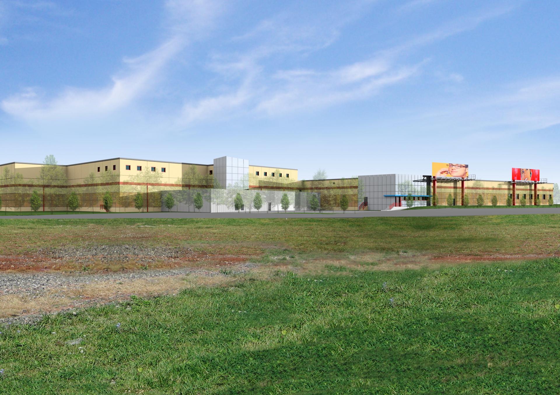
Summary: SIGMA7 design group, an integrated architectural and engineering firm with a practice focused on mission critical facility development, design, and delivery, played a crucial role in the expansion of the Carteret Colocation Data Center in Carteret, New Jersey. The master plan developed for the expansion of this Colocation Data Center, would ultimately double the size of the existing 80,000SF facility, at the completion of the 3rd phase of construction.
The expansion of this Colocation Data Center was master planned and developed by SIGMA7 as three (3) phased additions to enhance and complement the existing 85,000 square foot legacy data center.
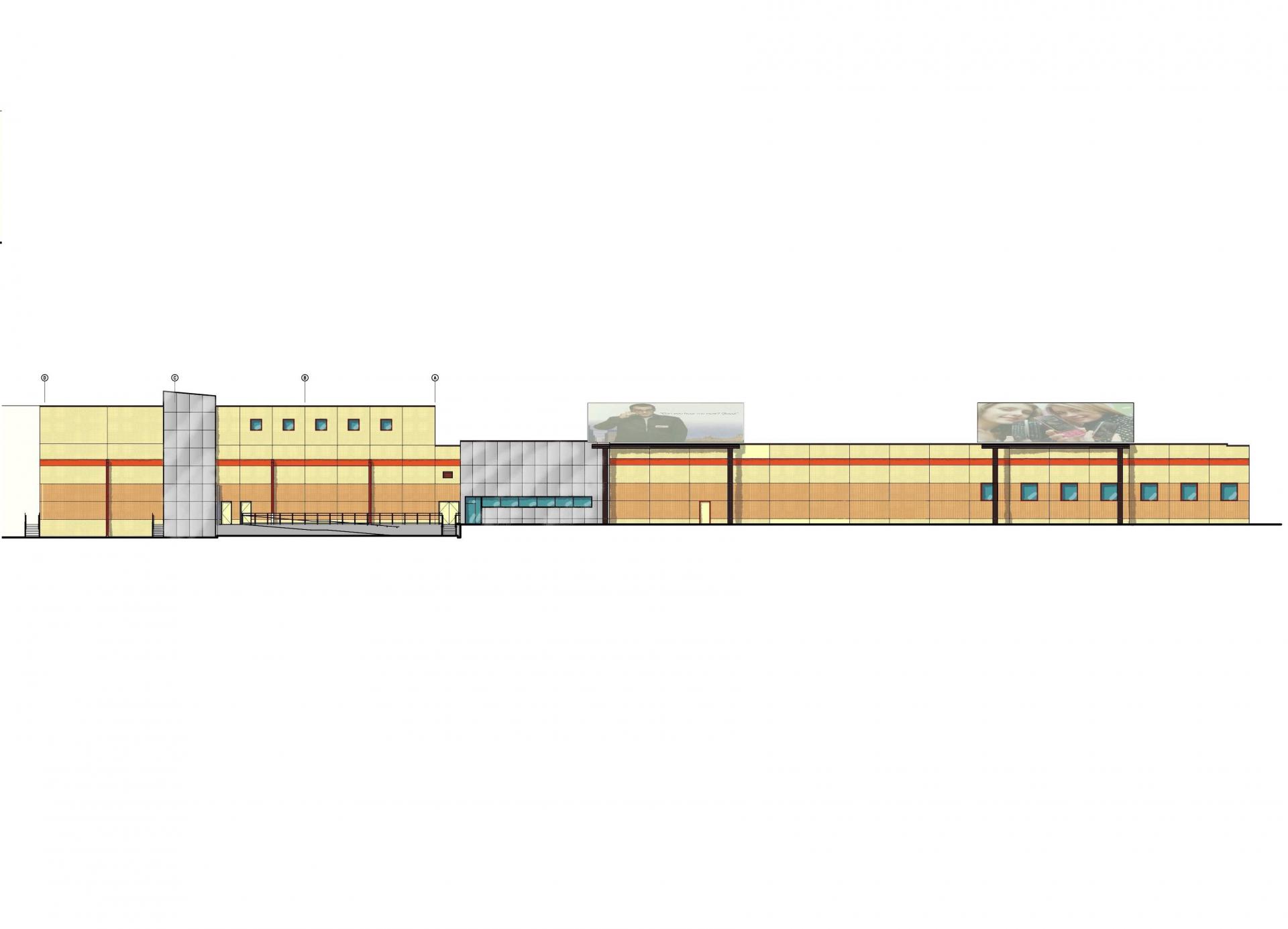
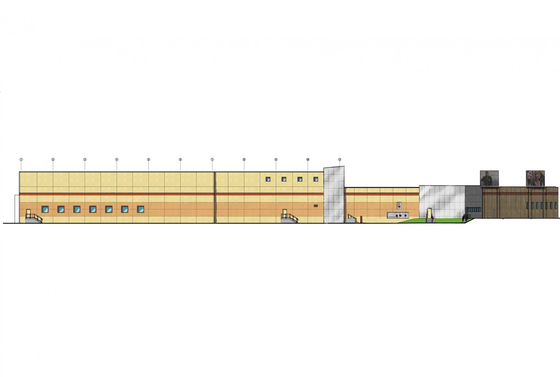
Phase I of the plan implemented a 28,000sf addition to the existing data center. Phase II, an additional 32,000sf that was constructed in sequence with Phase I. Phase III, the final phase of the program, incorporates an additional 30,000sf of production space. The master plan, upon its completion, nearly doubles the size of this facility, implementing an additional 80,000sf of available space and resources.
The building structure is structural steel frame system with 40’ x 25’ column bays. The hardened shell is fabricated from reinforced precast concrete, designed to withstand hurricane and tornado forces in excess of 150 mph.
The Electrical Infrastructure and related systems have 2N system redundancy in Phase I and a 3N/2 configuration in Phase II, with concurrent maintenance and monitoring of the entire electrical infrastructure. A rotary UPS diesel power generator system was utilized for Phase II with the Mechanical loads backed up on that system.
The Mechanical Cooling Infrastructure is designed with the use of air-cooled chillers and dry coolers for free cooling during low temperature periods. This system saves considerable energy whenever the air temperature is 60 deg F. or lower which occurs approximately 4,500 hours/year. The air-cooled chillers and dry coolers operate on a glycol closed loop system, resulting in reduced water usage and sewage discharge. This provides an important environmental and added financial benefit for the operation of this facility.
Phases I and II share the refrigeration plant and a common air plenum for ultimate redundancy and capacity. The AHUs are roof mounted, VAV controlled, and supply the raised floor via a common vertical plenum within the center of the building. All chillers, pumps, and AHUs are provided with variable speed drives; the entire system is configured as N+1 redundant and has a redundant glycol pipe loop and is concurrently maintainable.


